18. October, 2023delish0
1. Technical specifications;
| Use a power source | - |
| pressurized air | - |
| Slitting material | - |
| Slitting raw material diameter | - |
| Slitting width | - |
| Slitting speed | - |
| Device dimensions | - |
| Device weight | - |
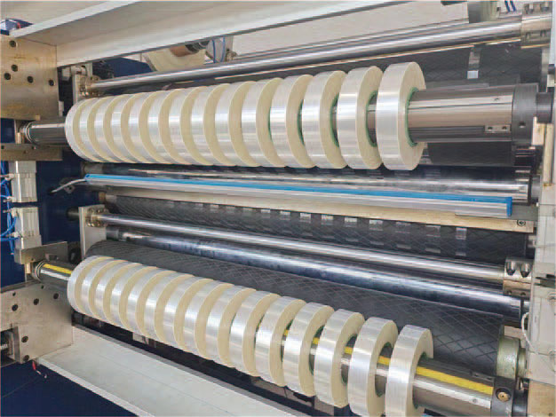
2. Structure and slitting flow chart;
1. Semi-finished products of tape machine
2. Adjustment mechanism
3. Press roller
4. Label roll
5. Unwind the spindle
6. Industrial knife inverted seat
7. Tension adjustment roll
8. Flattening and rolling
9. Guide roll
10. Margin material reeling shaft
11. Finished product coil shaft
III. Safety Rules:
1. Thoroughly understand the functions of this machine, please read the manual carefully before operating the machine, understand the functions and limitations of the machine, and its potential dangers.
2. During machine operation, all safety covers shall not be removed arbitrarily.
3. Before the machine starts, all adjustment tools should be removed.
4. Keep the workplace clean, dirty working environment can easily lead to danger.
5. All children and visitors should keep a safe distance.
6. Machine maintenance, service or replacement, etc., the total power supply should be turned off.
7. Before inserting the power plug, be sure to confirm that all switches are in the "OFF" position.
8. When any required parts are damaged, they must be replaced in time to ensure the operating performance of this machine.
9. During the operation of the machine, the operator shall not leave at will, if you need to leave temporarily, please stop the machine.
4. Clean and wipe test:
This machine has done perfect anti-rust treatment before leaving the factory. When you receive the machine unboxing, please wipe the rust oil of each part thoroughly. Please wipe the anti-rust oil with a dry cloth soaked with diesel fuel, do not use car oil or any other volatile solvents to wipe to avoid damaging the painted surface.
5. Level calibration:
1. The machine can be placed on the hard floor, and there is no need to use the foundation screw to lock the base in the floor.
2. This machine needs to do level calibration, please use a precision level to place the light roller, measure its level error, and adjust to the appropriate level by adjusting the horizontal screw at the lower end of the base.
3. The left, right and middle 3 points of the light scroll wheel need to be measured horizontally to adjust to the appropriate level.
6. Electrical control panel:
1. Power switch: turn the switch to the right, the machine can be started, and the open concern to the left,
The power is turned off.
2. Automatic/manual switch: use the switch as an automatic or manual exchange operation to control the exchange shaft. If the opening is placed in the "automatic" position, the shaft will be automatically exchanged after the winding operation is completed; If the opening is placed in the "manual" position, the "manual roll change" switch needs to be pressed to exchange the shaft after the winding operation is completed.
3. Host inch switch: press this switch, the host motor will start running.
4. Secondary start switch: After labeling and pressing this button, the host can start the rotation again.
5. Manual change left and right roll switch: Press this switch to change the roll manually, but the "automatic/manual" key must be cut to the "manual" position to have this effect.
6. Stop: Press this switch, the host motor stops running.
7. Speed adjustment knob: used to adjust the running speed of the host motor.
8. The host rotates: press and hold this button, the host runs slowly;
It can be stopped when loosened, making it easy to pierce the film.
9. Tachometer: host motor speed.
10. Counter: the number of secondary volumes.
11. Length counter: tape reel length setting.
VII. Confirmation of start-up operation:
1. Whether the machine is installed firmly.
2. Whether the voltage is normal.
3. Confirm whether the mold meets the required specifications; Including slitter pads, molds, paper tubes and raw materials.
4. Load the ingredients.
5. Thread the reel through the paper tube and confirm whether the edges of the upper and lower paper tubes are aligned.
6. Adjust the left and right position of the tool holder.
7. Adjust the left and right positions of semi-finished products.
8. Membrane piercing steps:
1. The tape passes through the pressure roller, single, pasted on the embossing roller, through the labeling roller, bow roller.
2. Tape is attached to the outside of the two embossing rollers.
3. Rotate the tool holder, adjust the handwheel to pass the blade through the tape, and lock the knife shaft.
4. According to the main inch, the tape has been striped at this time. The separate tape is attached one by one to the paper tube on the upper and lower roll shafts, and the offcuts are wrapped around the paper tubes on the scrap shaft.
9. Blade installation:
1. Loosen the locking screws at the left and right ends of the knife shaft.
2. Take out the whole tool holder.
3. Loosen the sleeve locking screw.
4. Remove the blades separately.
(Note: The blade is very sharp, and special care should be taken when removing the blade to avoid cutting your fingers.) )
5. Pour out the knife pad.
6. Select the appropriate width of the pad, load it into the knife tube, and then insert the blade into the middle of the two pads.
7. Lock the knife tube, lock the screw and the handwheel at the left and right ends.
8. Lock the locking screws at the left and right ends of the knife shaft.
10. Adjustment of blade slitting angle:
1. Loosen the blade tilt fixing screw.
2. Rotate the blade and tilt the handwheel so that the blade can just cut through the tape.
Rotate the handwheel counterclockwise, the blade leans forward, rotate the handwheel clockwise, and the blade is tilted back.
3. After adjusting the blade angle, lock the blade tilt fixing screw.
11. Length setting:
1. Length calculation and counter setting:
The diameter of the counting roller is 79.6 mm;
Circumference = diameter * ∏ (pi), 250 mm (1 yard = 914 mm)
Example: If the length of the finished product is 45 yards long, the counter should be set:
Then: 45 yards * 914 mm = 41130 (mm)
41130÷250=164.5(mm) (counter can be set from 164mm to 165mm)
2. Counter setting operation steps:
(1) The first paragraph is set:
If the machine is run to 1000 times to stop, the settings are as follows:
Press the M key, press the 4 key, if the original setting is a three-digit number, the number displayed in the fourth digit of the lower display window is 9, continue to press the 4 key, press the fourth digit once decremented once, until the fourth digit of the display window becomes 1, stop pressing this key, the number on the other digits changes the same until the lower display is 1000, and then press the E key, the first paragraph is completed.
(2) The second paragraph sets:
Press the M key twice, and then press the 3 key, the number setting method is the same as the above number setting, the number size is 5 less than the third paragraph number, that is, the second paragraph setting makes the lower display window display 995, and then press the E key, the second paragraph setting is completed.
(3) The third paragraph is set:
Press the M key three times, and then press the 3 key, the number setting method is the same as the above number setting, the number size is 25 less than the second paragraph of the number, that is, the lower display window shows 970, and then press the E key, the third paragraph setting is completed.
After the machine is running, the display window on the counter starts counting, when the number reaches 970, the machine starts to slow down, when it reaches 995, it stops running, and after pressing the second start, the machine stops when it runs at low speed to 1000, and after two seconds, the counter resets.
3. Three-segment counter display and button function description:
(1) The left side of the counter panel are two display windows, the upper display window shows the length reached by the machine after the last zero, and the lower display window shows the set number of lengths required to make the machine run. A, B, C are digital arrival signal lights, the first section makes the technology reach the set number, A signal light on; When the second actual number reaches the set number, the B signal light is on; When the third actual number reaches the set number, the C signal light is on. After the C signal light is on for 2 seconds, it automatically returns to zero and returns to the digital counting state.
(2) The right side of the counter panel is the setting operation button. Buttons 1, 2, 3, 4, 5, and 6 are set keys for digits, ten, hundreds, thousands, thousands, and 100,000 digits, and the other three buttons are function keys.
12. The function and use of bow roller:
The bow roller is a bent and rotating rubber roller, which can be rotated 360° when the material cannot be flattened, so that the material reaches no unevenness.
XIII. Semi-finished product loading and unloading and unwinding adjustment:
1. First align the left vertebral bolt of the unwinding reel with the appropriate hole on the shaft to lock.
2. Rotate the right vertebral nut so that the vertebral body is evenly buried in the paper tube segment, and the combined unwinding reel is loaded on the unwinding frame.
3. The right end gear and the brake gear bite, and the positioning groove at the left end of the shaft needs to be able to jam the bearing.
4. The unwinding reel can be adjusted left and right, please rotate the adjustment handwheel when adjusting.
14. Loading and unloading of reeling shafts:
1. After the finished product is cut, the reeling shaft can be removed.
2. Push the latch, clockwise, and relax the chuck.
3. Push the reel slightly to the right to remove the reel.
4. When installing the reel, please reverse the operation according to the above method.
15. Sequence of operation of strips:
1. Power switch, at this time the power indicator is on, and the counter shows "0".
2. Press the host start button, rotate the host speed control button, the host starts to rotate the slit, the counter can be counted, and the tension and bow roller are investigated according to the winding effect.
3. The host starts buffering until it stops, labels at this time, and then presses the second start again after labeling until it is suitable for rolling. Adjust the speed control knob back to the zero position, press the roll to start in place, cut, change the shaft and then rotate the speed control knob to work.
16. Exceptions and handling:
1. The semi-finished product produces wrinkles when winding, and the pressure of the tension cylinder can be appropriately increased.
2. When the finished product is rolled, whether the tension of the reeling shaft is too tight or related to the glue when gluing.
3. When the middle of the semi-finished product is relaxed, this is closely related to the uneven gluing and uneven substrate, at this time, the bow roller should be adjusted to flatten it, or the unwinding reel tension should be increased, and the substrate should be compacted with a knife tube.
4. Induction switch function and adjustment:
(1) The induction switches of this machine are fixed-point and do not need to make any adjustments.
(2) Counter induction: four-point sensing, with three-stage length. Counter for smooth braking and precise control.
(3) Exchange axis induction: once each axis change, the counter accumulates once in order to calculate the number of finished products.
5. Scroll tension setting:
(1) The tension of the tape on the reeling shaft is controlled by the tension adjustment nut.
(2) Rotate the nut clockwise, the tape is tightened, rotate the nut in the counterclockwise direction, and the tape is relaxed.
6. Handling of non-parallel reeling shafts:
(1) Check whether the left and right sprockets are loose.
(2) Install the four reeling shafts, make horizontal adjustment on both sides, correct the position, rely on the adjustment screws on both sides of the internal sprocket on the right side, first adjust the left side, adjust to the desired angle, and then adjust from the right side to the horizontal.
7. Scrap winding and adjustment:
(1) Adjust the bushing on the edge material shaft appropriately to align it with the edge material position.
(2) First operate manually until enough offcuts can entangle the offcuts and roll the shaft.
(3) When the machine starts the slitting operation, the offcuts will be automatically reeled
17. Maintenance:
1. Regularly check the embossed roller and unwinding brake pad, and replace it immediately when the brake pad is found to be excessively worn.
2. Each transmission sprocket and chain are often filled with oil, and butter or grease is added to the worm gear.
3. The internal gears of the gear pack are lubricated with butter when the machine leaves the factory, and there is no need for additional lubrication.
4. Check whether there is air leakage in each air path, and if there is air leakage, replace the joint or sealing ring.
5. The water distribution filter should often release water, and the lubricator should be frequently filled with light engine oil.
6. The machine should be wiped frequently, keep it clean, and it is absolutely forbidden to stick tape on the machine.


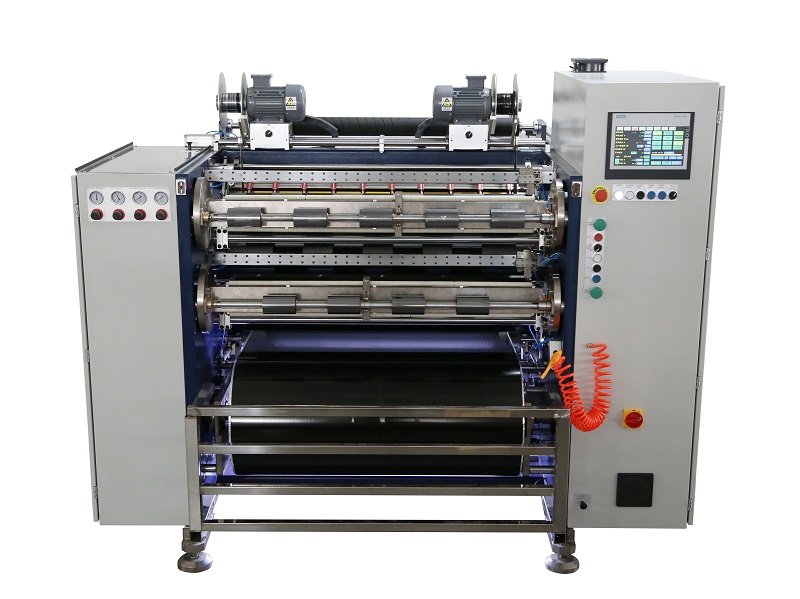 Fully Automatic TTR Slitter RSDS8 Plus
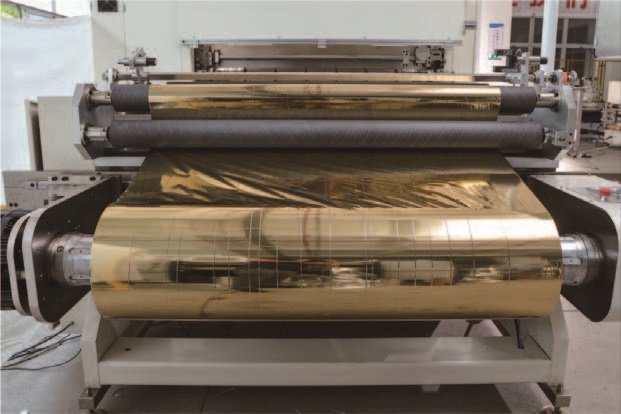
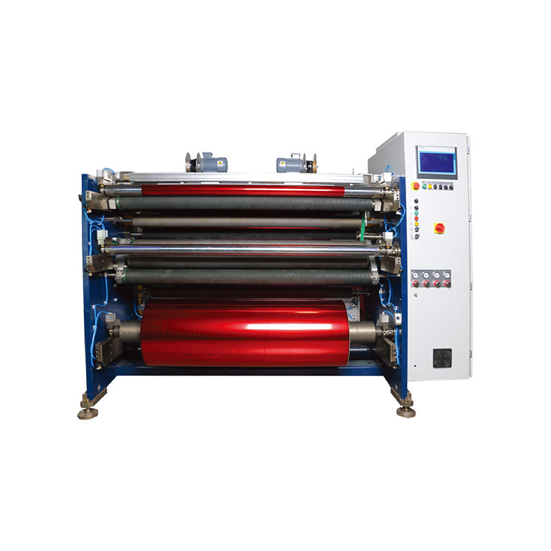 Hot Stamping Foil Slitter 1600mm
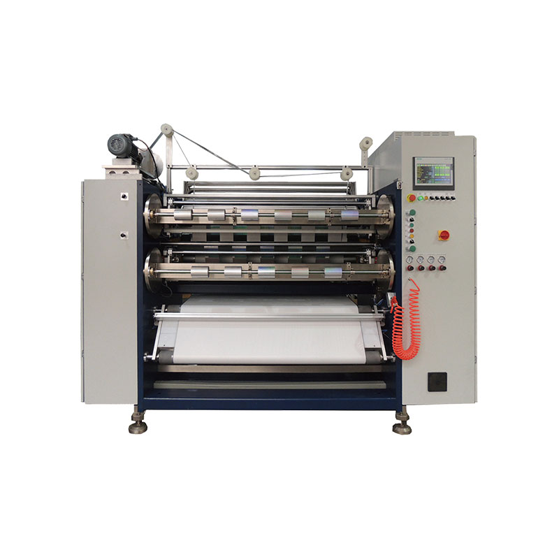 Hot Stamping Foil Slitter (4 Shafts)
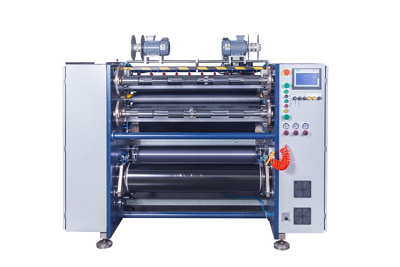 Semi-Auto TTR Slitter RSDS2 Plus
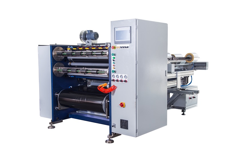 Semi Automatic TTR Slitter RSDS5 Plus
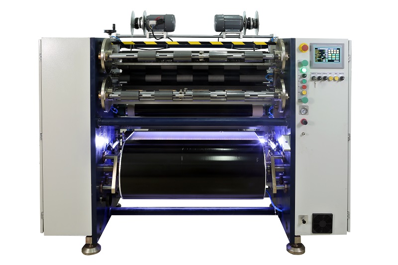 Manual TTR Slitter RSDS2
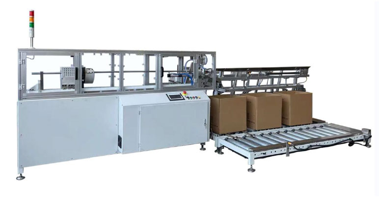 Auto Paper Core Cutter
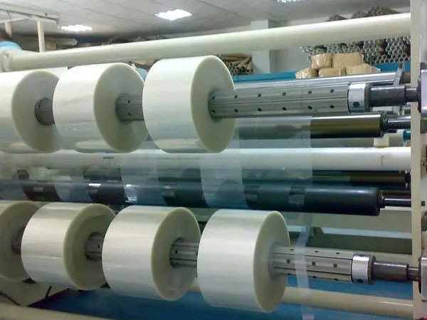 Film Slitting Machine


 +86 135 9951 7291
 support@delishgroup.com
 +86 135 9951 7291