07. August, 2026delish0
Introduction
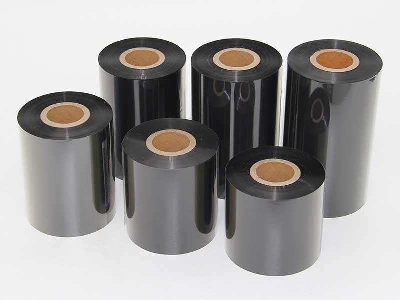
Heat transfer ribbons are indispensable consumables in fields such as barcode printing, label labeling, and packaging printing, and their quality directly affects print clarity and print head lifespan. In the ribbon production chain, the slitting and winding process is the core link determining the final product quality—the wide ribbon master must be precisely divided into narrow rolls suitable for different printer specifications, and the end face must be kept flat and tension uniform during the winding process.
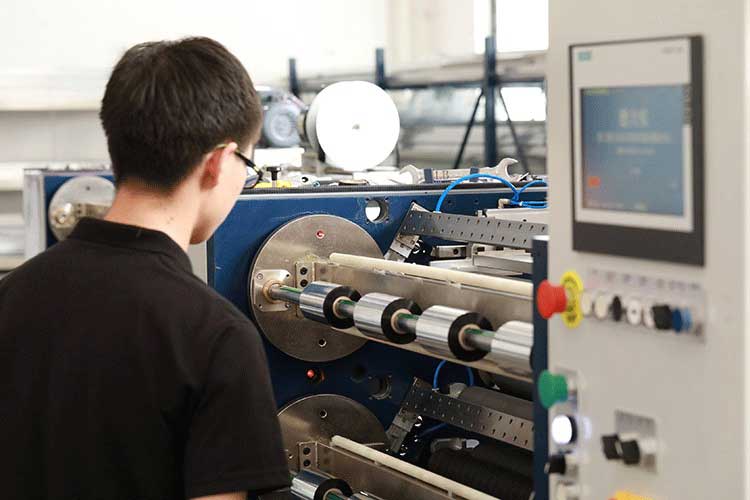
The technical difficulty of this step lies in the fact that the ribbon substrate is PET film only 4.5~10μm thick, which is extremely sensitive to tension, and any slight deviation during slitting can be magnified as a defect in the finished product. This article will systematically analyze the core technologies of the thermal transfer ribbon slitting winding device from the perspectives of winding mechanism design, tension control system, correction and guidance system, and slitting tool configuration.
1. Structural composition and workflow of the slitting winding device
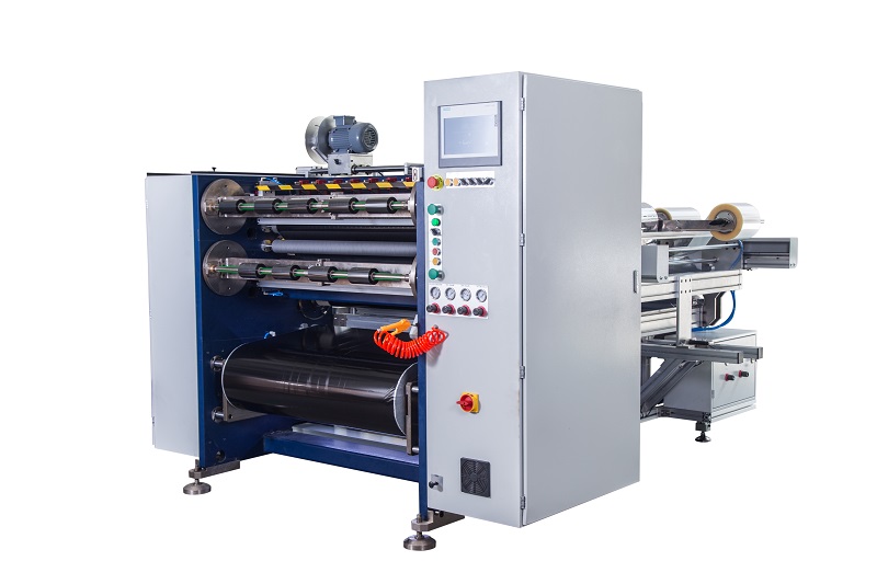
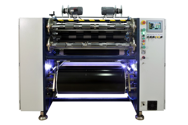
The basic structure of the ribbon slitting machine follows the process flow of "unwinding—slitting—winding," mainly including the following units:
• Unwinding device: supports wide ribbon main rolls (usually 500~1050mm wide), equipped with tension control mechanisms to ensure smooth roll unfolding;
• Correction system (EPC/CPC): Real-time detection of ribbon edge position via photoelectric or ultrasonic sensors, automatically adjusting the horizontal position of the header to ensure the cutting line is parallel to the edges;
• Slitting unit: uses circular or flat blades to simultaneously cut the wide female roll into multiple narrow strips;
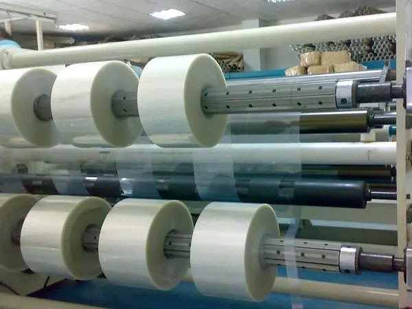
• Winding device: multi-axis synchronous winding, winding the slitted narrow strip onto the small core separately;
• Auxiliary systems: including static elimination rods, dust removal devices, roller systems, etc.
In actual operation, after the mother roll is positioned and corrected, it enters the slitting zone, is cut into multiple narrow carbon ribbons, and then is wound separately into finished products by independently controlled rewinding reels. The entire process must maintain micron-level precision during high-speed operation (200~300m/min, with high-end models reaching 400~500m/min).
2. Selection and Design of Winding Mechanisms
The winding mechanism is the direct actuator that determines the flatness of the finished roll end face, and its structural design and component precision are crucial.
1. Winding shaft type: slip shaft vs. gas expansion shaft
The selection of the winding shaft directly affects the consistency of multi-station winding. Currently, there are two mainstream solutions:
Slip shafts are the preferred choice for those seeking high flatness. Each slip ring can independently control torque. When the roll cores have uneven tension due to tube size tolerances, the slip rings automatically slide, ensuring that each roll is wound under the same tension, fundamentally eliminating the phenomenon of "loose inside, tight outside" or "tower-shaped."
Although ordinary gas expansion shafts are relatively low-cost, the tension at all stations is completely synchronized, making it impossible to compensate for the dimensional differences in the core coil itself. The more winding layers there are, the more pronounced the cumulative effect of uneven end faces. This issue is especially prominent for narrow band slitting (width ≤ 10mm).
2. Precision requirements for the winding reel
The radial runout of the winding shaft directly affects the ribbon's trajectory. High-quality equipment typically controls radial runout within 0.02mm, and the spindle must undergo dynamic balance testing to avoid periodic vibrations during high-speed operation. For large roll diameter winding (outer diameter ≥ 300mm), this indicator needs to be further tightened to within 0.01mm, because the ribbon with large roll diameter can weigh tens of kilograms, and any micron-level eccentricity will be amplified at high speed.
3. Swing arm roller pressing system
The pressure roller is an important auxiliary component to ensure winding flatness. The pressure roller relies on its own weight or cylinder pressure to continuously adhere to the surface of the rewinding film roll, serving two purposes: first, to expel air between layers and prevent slippage; Second, it suppresses radial runout of membrane rolls by maintaining constant linear pressure, especially effective during high-line speed operation. The parallelism between the pressure roller and the winding shaft must be controlled within 0.05mm/m; otherwise, the ribbon will shift in the same direction for each layer, ultimately forming a conical end face.
3. Tension Control: The 'Soul' of Slicing and Rewinding
Tension control accounts for over 50% of the impact on winding flatness, making it the core technical key for ribbon slitting. Excessive tension stretches the PET base film, causing microscopic cracks in the ink layer and powder shedding during printing; If the tension is too low, the roll becomes loose, causing wrinkles and white lines or indentations during printing.
1. Full closed-loop tension control vs. open-loop control
Modern high-end equipment commonly adopts a fully closed-loop tension control system, which uses tension sensors to detect the actual tension of materials in real time. After controller calculations, the winding motor torque is automatically adjusted to form a negative feedback closed loop. Open-loop control (such as relying solely on magnetic powder clutch adjustment) cannot cope with tension fluctuations caused by changes in coil diameter, inevitably resulting in uneven winding end faces.
Compared to traditional mechanical synchronous methods, the servo motor independently drives winding and unwinding, offering faster response and higher control precision, and can precisely control dynamic tension during acceleration and deceleration.
2. Taper tension control: The key to winding large diameters
As the winding diameter increases, if constant tension is maintained, the outer material will exert excessive pressure on the inner layer, leading to "rib bursting" or end face overflow. Taper tension control technology solves this problem—the system gradually reduces the winding tension according to the current roll diameter according to preset curves (linear, logarithmic, or exponential decrease), achieving a reasonable distribution of "tight inside, loose outside."
Typical parameters are: initial tension 8~12 N/m, final coil tension reduced to 3~5 N/m, taper coefficient 30%~50%. This technology is especially important for large diameter winding (outer diameter ≥ 300mm), increasing the pass rate of end face misalignment from 78% to over 96%.
3. Three-stage gradient tension strategy
To address the differences in tension requirements at various slitting stages, the industry has developed a three-stage gradient control strategy:
• Release area: maintains stable base tension;
• Slitting zone: Tension reduced by 10%~15% compared to the unwinding zone, minimizing material tensile deformation during cutting;
• Winding zone: The initial tension is 120% of the slitting zone, and decreases linearly to 80% as the roll diameter increases.
For narrow slitting, the unwinding tension should be reduced to 60%~70% of conventional broadband to prevent the ribbon from being "pulled thin" and dislodged from the slot.

4. Correction System: The core line of defense to prevent deviation
During slitting, ribbons are prone to lateral displacement due to factors such as uneven material thickness and blade resistance differences. An automatic deviation correction system must be installed, and the centering actuator should be located between the slitting tool holder and the winding shaft.
Correction accuracy is a key indicator: high-quality equipment can reach ±0.1mm, with a response time of less than 0.5 seconds. Regarding sensor types, ultrasonic types are suitable for thick substrates (above 6μm), while photoelectric types are suitable for thin substrates (4.5μm and below). Selection should be based on material characteristics to avoid false triggers caused by edge burrs.
On the operational side, the tape threading path must ensure that from unwinding to winding, it is absolutely perpendicular to the centerlines of each guide roller and tool groove—even a 1° deviation will be amplified at high speeds.
5. Matching slitting tools with the process
The choice of tool directly affects the quality of the cut and the condition of the winding end face. For PET substrate ribbons, circular blade slitting is more suitable—using a top-down blade cutting method, resulting in low shear force, smooth cuts, dust-free operations, and long tool life. If a flat blade (razor) is used for slitting, uneven edge wear can cause edge burrs or stretching deformation, which can lead to edge warping during winding.
It is recommended to adjust the blade angle to 15°~20°, using single-sided beveled cutting to reduce edge stress. The gap between the blade and the groove should be controlled at 0.02~0.05mm, and the sharpness of the blade should be inspected every 8 hours. For thin ribbons (<8μm), the initial slitting speed is recommended to be ≤50m/min, gradually adjusting to the optimal parameters; Brittle materials can be preheated to 40~50°C to improve cutting performance.
6. Tail material management and scrap rate control
Tailstock waste is a commonly overlooked loss during ribbon slitting. In traditional processes, when the slitting roll approaches the hollow paper tube, the diameter shrinks, causing tension instability, and the last dozen meters of carbon ribbon cannot guarantee quality and must be discarded. Industry practice shows that through technical optimization, the tailstock can be shortened from an average of 15 meters to within 5 meters, and the proportion of tailstock in the total slitting volume drops from 2.1% to 0.7%.
The implementation path includes: when the coil diameter is less than the set value (e.g., 50mm), it actively switches to "small roll diameter mode" to significantly reduce tension; Installation of a light-touch pressure roller compensates for insufficient support at the core of the roll; The collected, surplus material is spliced by a dedicated tape stapling machine and sold as samples or low-cost test tapes.
By comprehensively applying fine tension control, real-time correction of the correction system, tool process optimization, and special management of tailstock, industry cases show that the defect rate can be reduced from 5%~8% to below 1.5%, and slitting accuracy can be improved from ±0.5mm to ±0.1mm.
Conclusion
The thermal transfer ribbon slitting and winding device may seem like just "cutting wide rolls into narrow rolls," but in reality, it involves the integrated application of multidisciplinary technologies such as tension control, precision machinery, automatic correction, and tool technology. From the selection of the slip shaft to the setting of the taper tension curve, from the rollout accuracy of 0.02mm on the winding shaft to the positioning capability ± 0.1mm in the correction system, every detail affects the final ribbon performance in the printer.
For equipment selection, winding flatness is not determined by a single factor, but is the result of systematic optimization of the entire machine configuration. It is recommended to base the test on actual sample testing, focusing on core configurations such as tension control method, winding shaft type, and correction accuracy. For manufacturers, establishing a slitting process database and solidifying the optimal parameter combinations for different ribbons is a key path to continuously improving yield rates.
 English
 Deutsch
 Français
 Español
 Português
 日本語
日本語 русский
 한국어
한국어 عربي
عربي ภาษาไทย
 Tiếng Việt
 Italiano
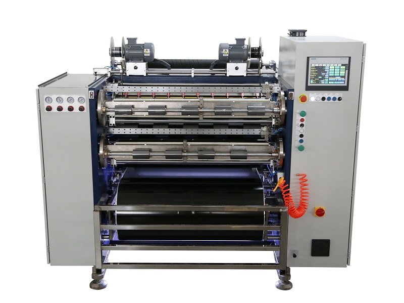 Fully Automatic TTR Slitter RSDS8 Plus
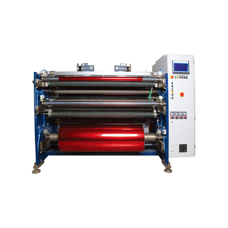 Hot Stamping Foil Slitter 1600mm
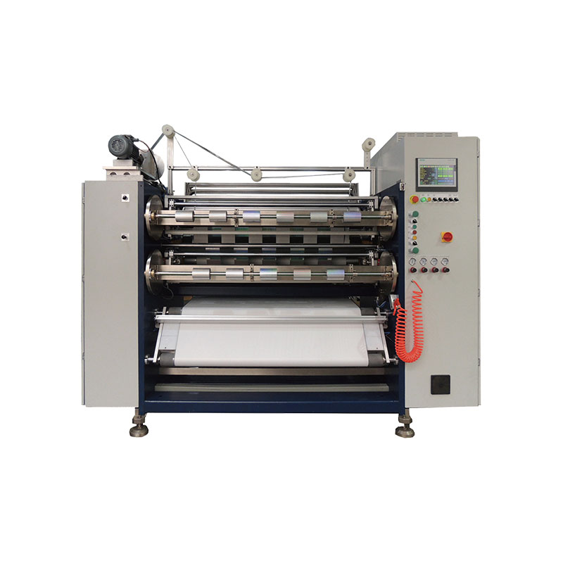 Hot Stamping Foil Slitter (4 Shafts)
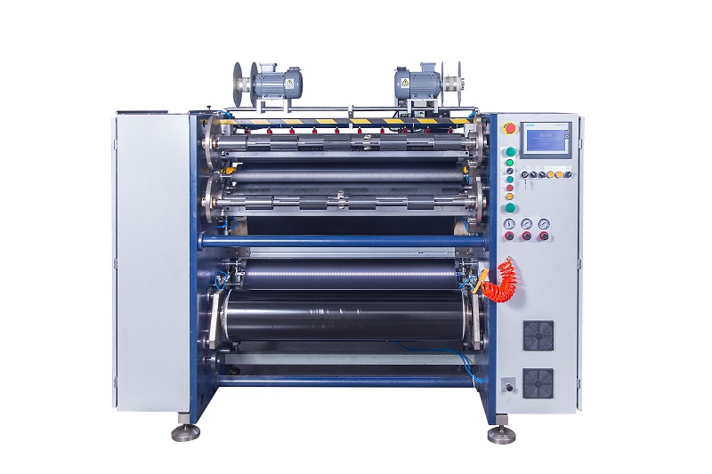 Semi-Auto TTR Slitter RSDS2 Plus
 Semi Automatic TTR Slitter RSDS5 Plus
 Manual TTR Slitter RSDS2
 Auto Paper Core Cutter
 Film Slitting Machine



 +86 135 9951 7291
 support@delishgroup.com
 +86 135 9951 7291