16. November, 2026delish0
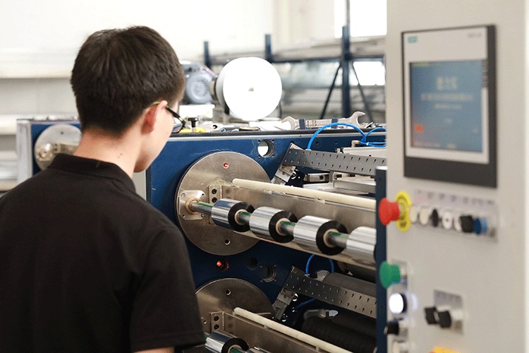
The width accuracy of a ribbon slitting machine is usually measured by the tolerance between the actual width of the narrow strip after slitting and the target width. High-end models can keep this tolerance within ±0.05mm, while ordinary equipment often hovers between ±0.3mm and ±0.5mm. Although the difference seems minor, it directly determines the smoothness of the ribbon movement and printing lifespan in the printer—narrow strips with excessive width can at best wrinkle and misalign, or at worst break under uneven force at the edges during high-speed printing. To understand the principles of width precision control, it is necessary to move beyond the single perspective of "whether the tool cuts accurately" and view the slitting process as a four-dimensional coupling system engineering involving tension, guidance, tool, and inspection.
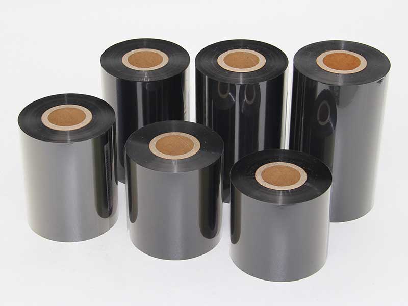
1. Tension Closed Loop: The first line of defense for width accuracy
The ribbon substrate is PET film with a thickness of only 4.5 to 12μm. Its extremely thin physical properties make it exceptionally sensitive to tensile forces. If the tension is too high, the base film becomes elastic or even plastically elongated, causing the width to shrink after slitting, resulting in actual dimensions smaller than the target value; If the tension is too low, the material becomes loose and wrinkled, causing the lateral position to drift unsteadily, so the cutter cannot follow the predetermined trajectory.
Therefore, the foundation of width accuracy lies in independent closed-loop control of the three stages of tension: unwinding, traction, and rewinding. Modern high-precision slitting machines use tension sensors to collect the actual strip tension in real time, feed it back to the PLC, and dynamically adjust the servo motor's output torque through PID algorithms. The response speed and steady-state accuracy of this closed loop directly determine the lower limit of width fluctuation. Traditional magnetic powder clutch control methods can fluctuate in tension up to ±10%, enough to cause batch width deviations at speeds of several hundred meters per minute; The servo closed-loop system can compress fluctuations to within ±0.25N to ±0.5N.
What's even more ingenious is the winding taper tension strategy. As the winding diameter increases, maintaining constant tension causes the outer carbon ribbon to exert excessive compressive force on the inner layer, leading to core deformation or even ink extrusion adhesion, indirectly causing unstable feed during subsequent slitting. Based on real-time calculated roll diameter, the system gradually decrements the winding tension according to a preset curve, keeping the narrow strip at an appropriate tightness from full roll to empty roll, providing stable end conditions for width consistency.
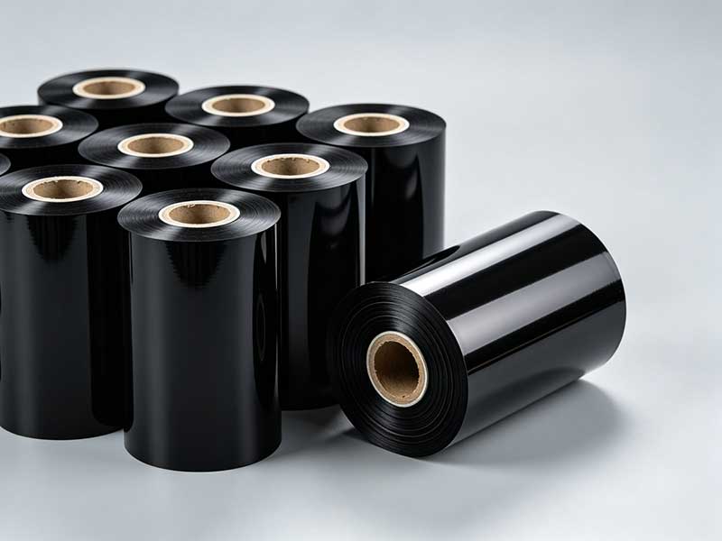
2. Correction and Guidance: Maintain the horizontal reference of the cutter
Before the ribbon enters the slitting knife, its edges must always remain fixed and in a known transverse position. Any slight lateral drift means the cutter has shifted relative to the actual cutting line of the ribbon, making width accuracy impossible.
The involvement of the Automatic Correction System (EPC) is precisely to bring this variable into a closed loop. The principle is not complicated: photoelectric or CCD sensors continuously scan the lateral position of the ribbon edge, convert the offset into electrical signals and transmit them to the controller, which drives servo motors or pneumatic mechanisms to push the uncoiling rack or straightening guide roller for lateral fine adjustment, "pulling" the strip back to the correct reference. Current mainstream solutions achieve dynamic correction accuracy of up to ±0.1mm, and even higher in high-end configurations. For ultra-narrow specifications with slitting widths below 10mm, the importance of correction becomes even more pronounced—the lateral rigidity of the narrow strip is extremely weak, and even a deviation of just a few dozen microns can render the finished product as scrap.
Working in conjunction with the straightening system is the high-rigidity guide roller system. The straightness of all rollers must be controlled within 0.01mm/m, radial runout is limited to the micron level, and strict parallelism must be maintained between them. Any eccentricity or skewness of the guide roller will be transmitted as lateral swing of the ribbon at twice its deviation magnitude. Correction addresses "offsets that have already occurred," while precision guide roller systems reduce misalignment at the source.
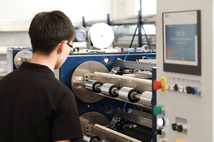
3. Tool System: Cutting mechanics in micron gaps
When tension and guidance create stable feeding conditions for the ribbon, the final step in width accuracy lies in controlling the tool and the tool pitch.
The essence of circular blade slitting is the cutting process of a pair of upper and lower cutter discs. The lateral clearance between the upper and lower blades is the core parameter determining the quality and width accuracy of the cut. If the gap is too small, the blade edges rub against each other, producing burrs and dust, and the edge of the cut is compressed and deformed; If the gap is too large, the material is torn instead of sheared, with tiny edges appearing and the actual effective width becoming unpredictable. For carbon ribbons only a few microns thick, this gap usually needs to be precisely controlled between 0.02mm and 0.05mm, depending on the substrate thickness and coating properties. The radial runout of the cutterhead is also crucial; if the spindle runout exceeds 0.005mm, the slitting width will fluctuate with the periodic deviation of the blade.
The tool pitch setting method has evolved from manual to CNC control. Early equipment relied on mechanical lead screws and dials for knife-by-tool adjustment, with gaps and positions relying on operational experience, resulting in limited repeatability. Modern high-end models use servo motors to drive axial displacement of the tool holder, with a resolution of up to 0.01mm. Combined with closed-loop position control, it completely eliminates positioning errors caused by reverse screw backlash. Some devices also integrate online visual inspection, with CCD cameras capturing the actual position of the slitting edge in real time, feeding width deviations back to the tool holder control system for dynamic compensation, turning the tool distance from a "set value" to a "verifiable real-time value."
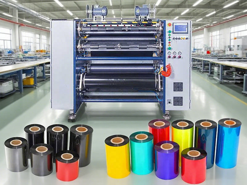
4. System Collaboration: Accuracy is the outcome, not an isolated metric
Breaking down the above steps, each technology has its own clear accuracy contribution: tension closed-loop suppresses tensile variables, the correction system locks the lateral datum, and the tool system determines the cutting geometry. However, achieving width accuracy ultimately depends on the dynamic coordination among the three factors.
A typical example is parameter coupling during narrow-band slitting. When the slitting width drops below 10mm, the lateral rigidity of the ribbon drops sharply. If the winding tension is still set according to conventional broadband, the material will be overstretched longitudinally and contracted laterally due to the Poisson effect, resulting in a narrower cut width and concentrated edge stress. Experienced process adjustments reduce the winding tension of narrow band slitting to 60% to 70% of the conventional value, while appropriately lowering the vehicle speed to provide a more ample response window for the correction system. This means that the control logic for width accuracy is not about each subsystem pursuing local optimization independently, but rather about finding a dynamic balance point among speed, tension, correction response, and tool distance.
As a result, a well-calibrated high-precision ribbon slitting machine can stabilize width tolerances within ±0.05mm, and reduce the defect rate from 2% to 3% of ordinary equipment to below 0.3%. For high-value ribbons such as resin-based and hybrid-based, the material cost savings and reduced downtime and commissioning time from improved precision are far more significant than the equipment's own performance parameters. The principle of width accuracy ultimately boils down to one sentence: ensuring that the ribbon's movement in every dimension before reaching the blade edge is within a perceptible, intervenable, and correctable closed loop.
 English
 Deutsch
 Français
 Español
 Português
 日本語
 русский
 한국어
 عربي
 ภาษาไทย
 Tiếng Việt
 Italiano
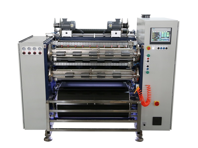 Fully Automatic TTR Slitter RSDS8 Plus
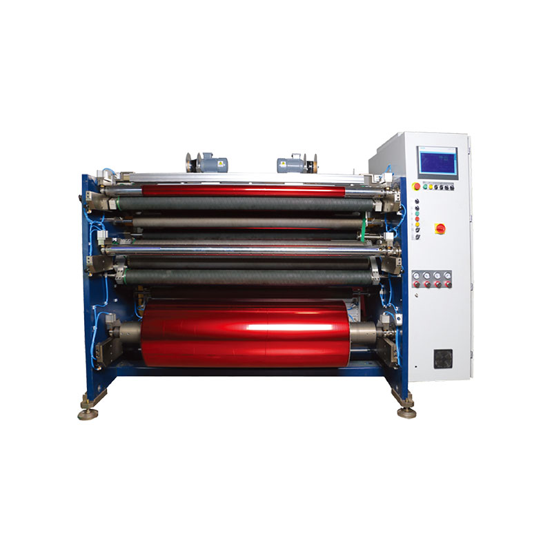 Hot Stamping Foil Slitter 1600mm
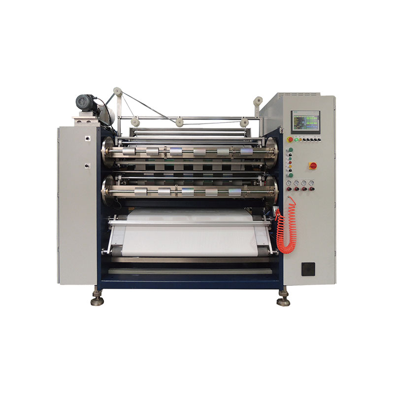 Hot Stamping Foil Slitter (4 Shafts)
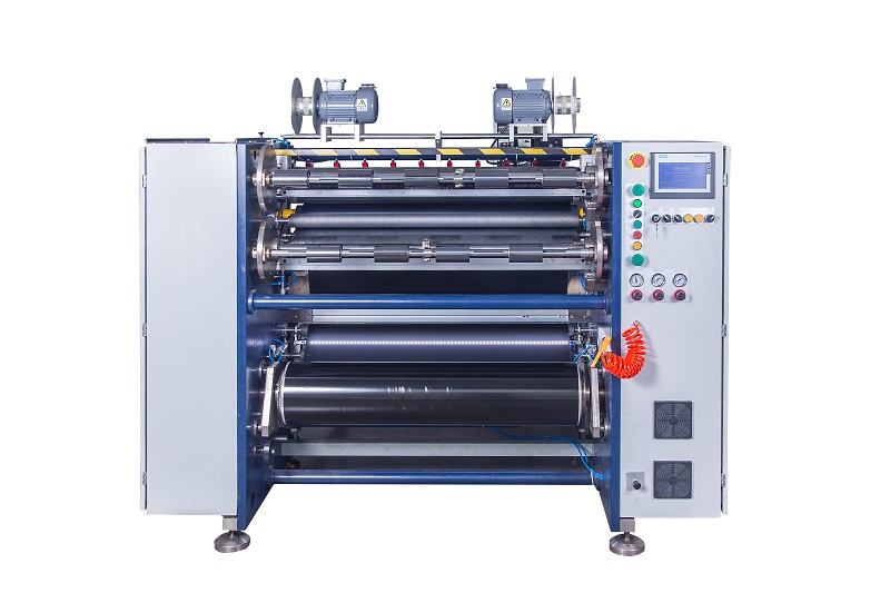 Semi-Auto TTR Slitter RSDS2 Plus
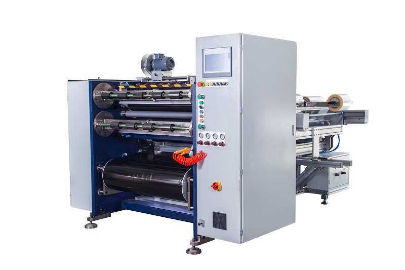 Semi Automatic TTR Slitter RSDS5 Plus
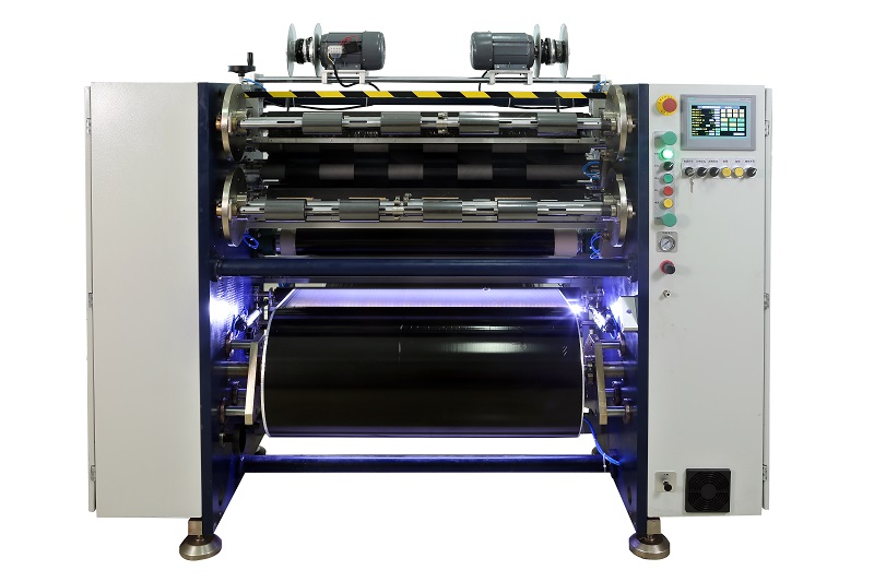 Manual TTR Slitter RSDS2
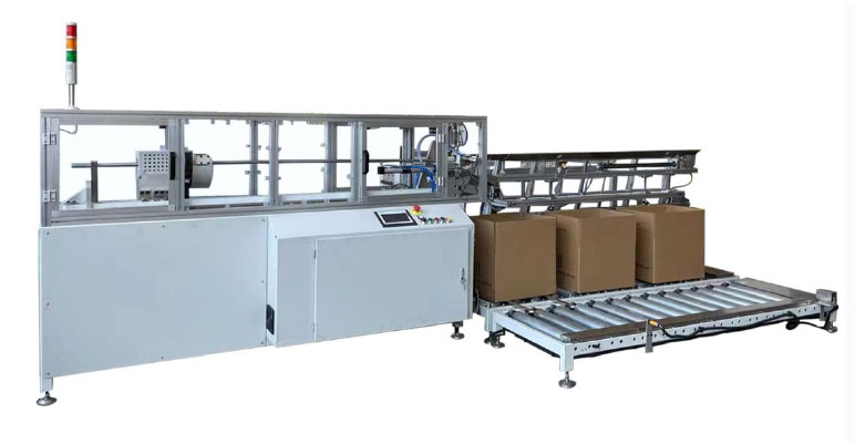 Auto Paper Core Cutter
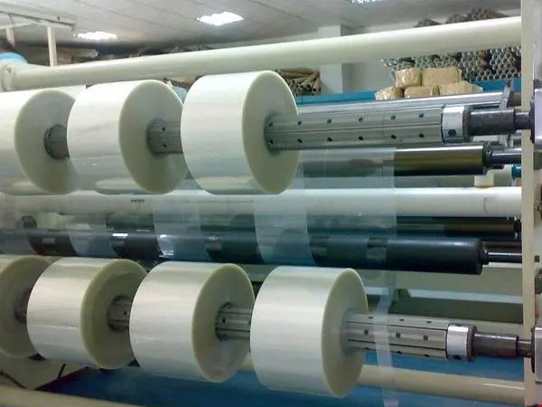 Film Slitting Machine



 +86 135 9951 7291
 support@delishgroup.com
 +86 135 9951 7291
